1 pair in series by the door, the third in series “internally”. Do you know what that means?
3 Likes
Does it really with a regulated mod? I’ve read mixed opinions so I’m confused to what the facts really are.
The site where I buy my batteries, fogstar.co.uk, is pretty reputable and they don’t take the coil in consideration when calculating what amps batteries you need on a regulated mod.

3 Likes
I do.
And without having the mod in front of me to disassemble and verify that, I put my opinion forth based on what I see (and noting such as a disclaimer, not a guarantee of fact).
Thanks for the video link though.
3 Likes
IMO it does. As it CAN (is supposed to) directly dictate the load seen by the mod, assuming everything is working properly within the mod.
You can only prepare against the things you are aware of in my experience. We’re all at the mercy of the unknown.
I’m not going to get into “what others do” with you.
There’ve been several examples of regulated mods having issues over the years. You take the precautions you see fit, and I’ll do the same.
3 Likes
Sorry if it wasn’t clear. I was asking because I don’t, kinda hoping you could explain 
2 Likes
I apologise. I thought you were having another go at me (by the way it was phrased, and after you politely asked me to “butt out” of another thread recently…)
I still haven’t had time to watch the video, and there may be something telling there (if he did a complete field strip)…but for the moment, I’m continuing to go on the picture (until I can watch the video on a solid connection).
In most of the mods I’ve seen (I’ve only been inside of a couple of three battery mods), the battery door connectors have not had a physical wire connection point. Normally, they’re one solid piece of metal, that connects whatever (everything that) contacts the connection points.
Which if that were the case with the pic I previously posted, would eliminate there being a need for a connecting wire that would go into the battery door, and would be a weak point, thanks to the flex-stress induced onto the wire from repeatedly opening and closing the door (changing batteries).
In fact, that’s the whole reason that most two battery mods use the little spring-loaded pressure contact in between the two batteries on the door. It eliminates the need for a wire going to the battery door contact bridge.
The sensor wire is hidden internally, but still makes it’s connection to the spring loaded piston as seen in the center, with it’s connection point in the center of the battery door (which in the case of the Alien, Cylon, and many others, is a single contact bridge bar inside the door, with no physical wiring to the mod through the door channel). Basically, the three ‘separate’ contact points seen on the door, are all one piece of metal. Intentionally covered by the material on top of them, to effectively shrink the surface area exposed to the battery contact points, so that IF a damaged wrap were in play…chances of creating an area to short would be further minimized than simply leaving the entire connecting bridge (underneath) exposed.
If they have in fact used a unique design of the battery bridge on this device (entirely possible), I’d be surprised as it’s unlikely due to fact that I would expect them to “have to” run a connecting wire through the flex-point of the door…I can’t currently picture any other way to do so offhand. And NO, this isn’t calling out DJLSB, saying he’s wrong (about what whatever is said in the video), etc. I’m simply saying that I haven’t seen it yet, and I can’t picture that being the case. I’m always open to learning something new, as well as being wrong.
But even drawing this out as a series circuit…
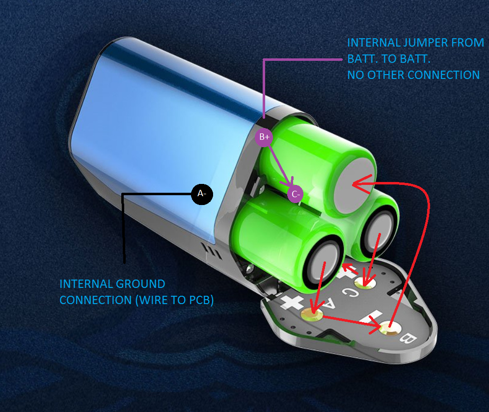
In my example above, there would be a ground connection expected (going to the pcb) at the negative side of battery A.
And a return wire (positive point of contact to complete the circuit) at “C+” (on the battery door). Which in effect means that there would have to be a wire going through the door channel.
Even if it was reversed (meaning: I drew it backwards), there would have to be a phsyical wire connected to “A+” going to the positive lead on the pcb (through the door channel). But there could be no connection between C and A on the battery door at any point, as that would create a parallel connection.
In which case, it would be a design flaw IMHO (as I would expect the life of the wire running through the battery door would dramatically shorten the expected useful life of the mod), or I’m wrong, it simply wasn’t done that way. In which case, again, I simply don’t have enough information to attempt a guess. I would need to have the mod in front of me to figure out exactly what’s being done.
What I would normally expect would be the following:
Hopefully this helps clear up what I was thinking, and why.
If I can get a decent enough connection to watch video on my phone, I’ll try and update if I find what I’m not getting, or was flat out wrong about.
5 Likes
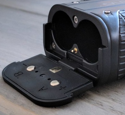
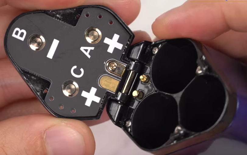
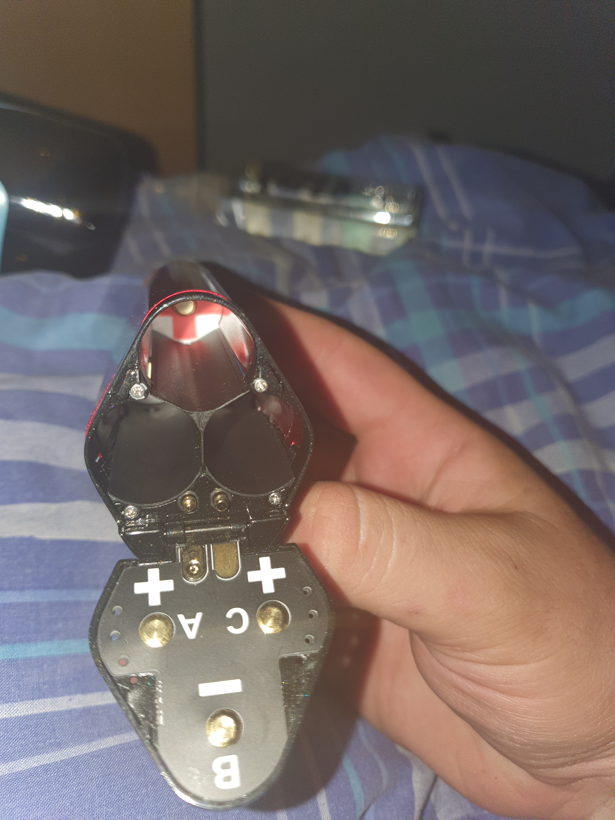
I didn’t quite see how it works in the video, but here’s a better picture of the door. Instead of the 1 pin (which I always thought was for balanced charging, even though I don’t get how it works), this mod has 2 pins. Maybe there’s a separation between the metal in the door that connects A/B and C? If that’s the case your first drawing would probably be accurate. No additional wiring required with the additional pin.
4 Likes
Thank you!
Great shot by the way.
The picture is slightly fuzzy around the other “shiny areas” (around the main mod, which faces the door), but I’m going to assume [gulp] that those are screws…since there are no mating points of contact in the battery door.
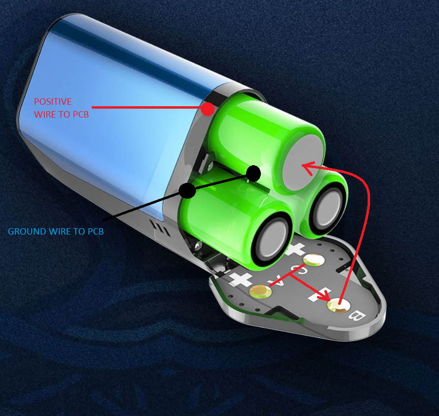
Under ‘normal’ circumstances, it is the pin that’s used to monitor the batteries (which is why I frequently refer to it as the “sensor” wire).
Because, the monitoring pin is located on the bridge (between the two batteries) depending on how the cpu switches the monitoring circuit (in other words, which battery it is sampling the voltage from) it allows the electronics to know which battery is at what point of progression during the charging process.
So it does!
Which would imply to me that they aren’t able to monitor each battery individually, but rather, appear to be using those two points of contact to facilitate the series connection. But again, this is educated guessing. Not an assertion of fact.
If they use those two contact points to effect a series connection, in conjuction with a custom bridge, things do seem to fall in line with the first sketch I submitted above. As the assumed (spring loaded) points of contact would be relative to points A and C, with a bridge between either A & B or C & B.
You got it!
I my hate guessing about such things (even educated guessing), as I try my damnedest to stay with factual statements… But I also want to try and help others gain a better understanding. Sometimes the two cross, which point I try to help to the best of my ability and understanding, but I try to make sure that folks understand which point of view I’m coming from (fact vs theory and/or educated guessing). I apologize for the times when I may fall short of this.
4 Likes
It was just a screenshot from DJ’s video, not taking credit for it. You’ll get a better idea if you have a look at it when you have the chance.
Anyways, thanks for the explanation. I think I better understand how these things work now.
3 Likes
Wow that wend alot deeper then i expected.
Thanks both of you for the info and time.
Ps the other bits opposite door are screws
3 Likes