Hehe, oh YES they hold a charge and will DISCHARGE at the drop of a hat !!!
Yes, yes, and MORE yes.
Ooooooh, I must have missed that, I didn’t know what you were building. Do you have multiple stages ?
Hehe, oh YES they hold a charge and will DISCHARGE at the drop of a hat !!!
Yes, yes, and MORE yes.
Ooooooh, I must have missed that, I didn’t know what you were building. Do you have multiple stages ?
Yep, it’s going to be a 2 channel power amp with no preamp stage. I’ll have to build or buy one or seperate the preamp section of my old NAD amp to have source selection, tone and volume control.
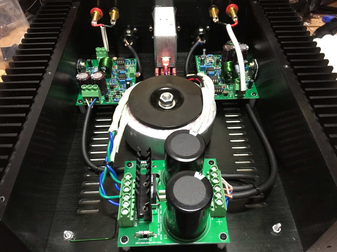
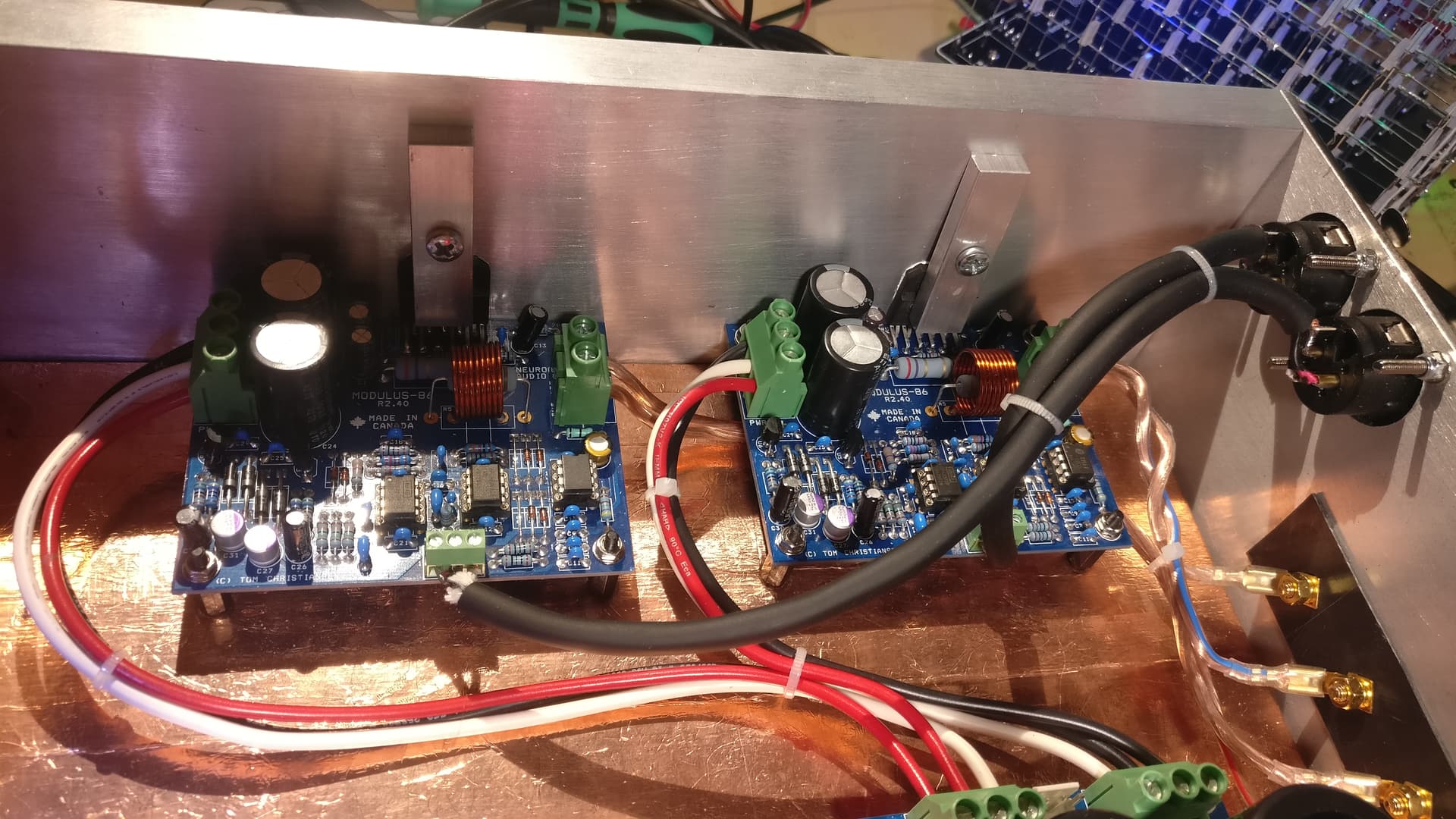
There’s one of these boards per channel
I hope it will look similar to this when it’s done.
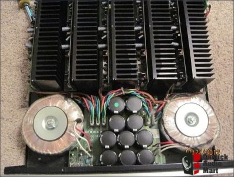
Wait JUST a second. Is that a toridial transformer I see there. Well, well, well. I’m liking this even more now.
I don’t build amps, but the last time I was really smitten with those transformers, I had to buy an Anthem MCA 5 with them in it !!!
Wow that is a big amp there…
Toroidal transformers are pretty much standard in these amps but there more switching power supplies now.
Edit: SMPS is what I meant - switching mode power supplies. The can be smaller because they run on high frequencies. But they have to be designed properly or they can introduce distortion if not properly filtered.
Just looked that one up, man that is a monster! 5x170W, I guess that’s on 4 Ohms but to 8 Ohms that must still be around 60-80W per channel. Are you running that with 4 Speakers and a center or a sub?
I like the balanced inputs. Not sure if that really makes a difference I could still hear with decades of factory work, clubs, live music, rehearsal rooms and ott sound in the car. But it opens the door to some pro equipment.
What you also could do with a 5 channel amp like this is to run a pair of speakers with a subwoofer. 2 Channels per Speaker, bypassing the passive crossover of the speakers and use an active crossover instead, something like this:
Apparently, that’s the way to go if you really want to tweak the sh*t out of your speakers. Makes measuring and configuring chrossovers an achievable task for people without a degree.
I mean, I’m still a fan of minimalistic hifi gear, a CD player or whatever source, a 2 channel amp and a pair of 2way speakers is usually all you need in a small room. And all analogue from the output of your source to the speakers. In the 80s and 90s all the electronic tone and volume control stuff sounded terrible but it came a long way since that time.
Maybe I’ll build a few more channels one day and go apeshit on the new digital stuff but for now I keep going analogue.
@Bad_Influence I think it’s rated @ 200w single channel driven @8ohms, 175w five channels driven @8ohms, and jumps up considerably @4ohms, 2ohms, etc.
I’m driving 5 channels off that amp, and the sub is a Reference 15" Servo, which has it’s own onboard amp.
I’ve tried to compare RCA with XLR and couldn’t hear much.
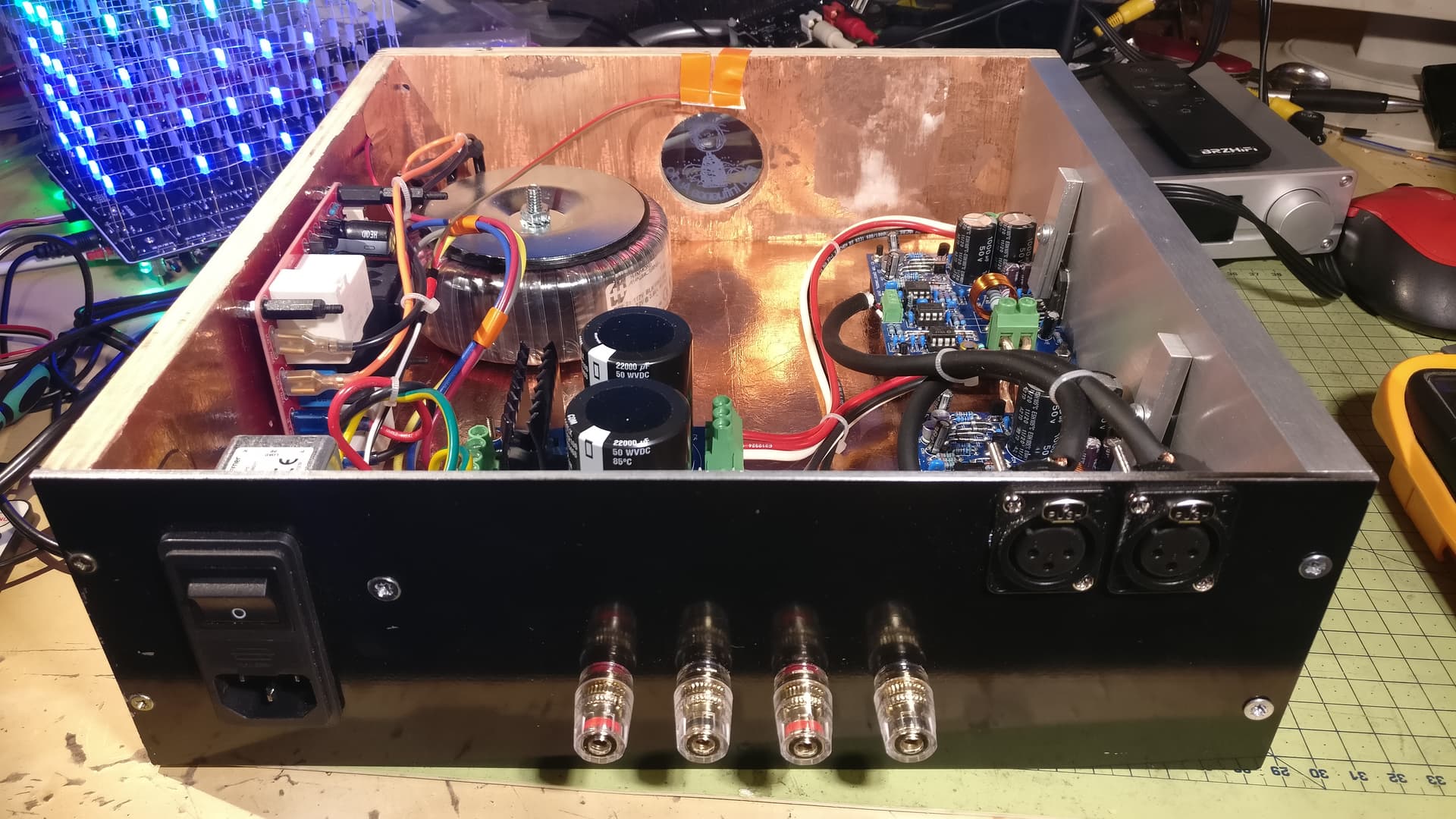
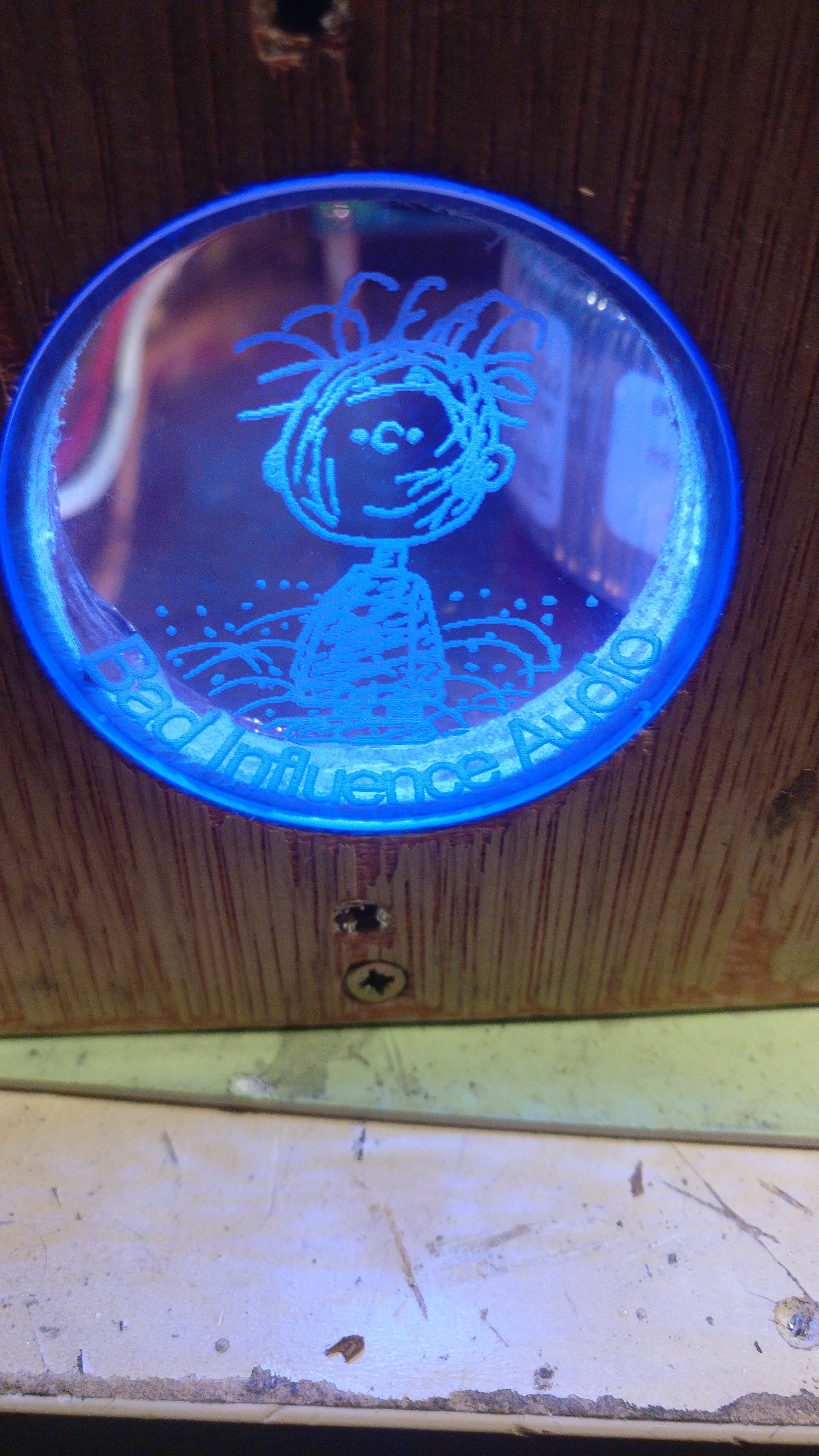
Right… so it’s been a while and i finished the build apart from a few cosmetic jobs. A new front panel, some paint and the logo doesn’t look so good yet. Oh and no lid yet so not living room ready yet. But all the electrical tests were successful including a PAT test so unless i stick my hand in while turned on it’s unlikely that I’d kill myself or set the house on fire.
Not connected to a source and speakers yet but that will follow the next few days.
@Bad_Influence, clean, clean, and MORE clean looking. Every time I see a toroidal transformer, I get interested. One of my FAVs (which is STILL in use) is my Anthem MCA-5, which has toroidals, and a pyramid of caps. Obviously that was a multi-stage MOSFET (I think), high gain 5 channel. I’m interested as to what’s what there.
I see stereo, is that a primary stage, followed up by two secondary gain stages ??
More, more, more !!!
Then we can invite @SmilingOgre over, and rack that thing up on the scope.
Sweet looking build! Can’t wait to hear the report on how it sounds. Thanks @SessionDrummer for the shout, but @Bad_Influence is on top of this with the tests he has run. Not that I wouldn’t mind comparing input to output signals just to do it.
E.X.A.C.T.L.Y.
#OgerVision
#ImWithOgre
#DontForgetTheScope
Got one coming for you soon. Got a couple of retakes to do. I hate me on camera.
Even though I did a hella lotta EE work, I never really spent huge time a low level design, but CAN indeed very much appreciate clean traces, layouts, designs, and just damned fine looking builds. Admittedly, the most I’ve used a scope lately, is for gain matching, setting amp clip levels, etc. Boring stuffz0rz.
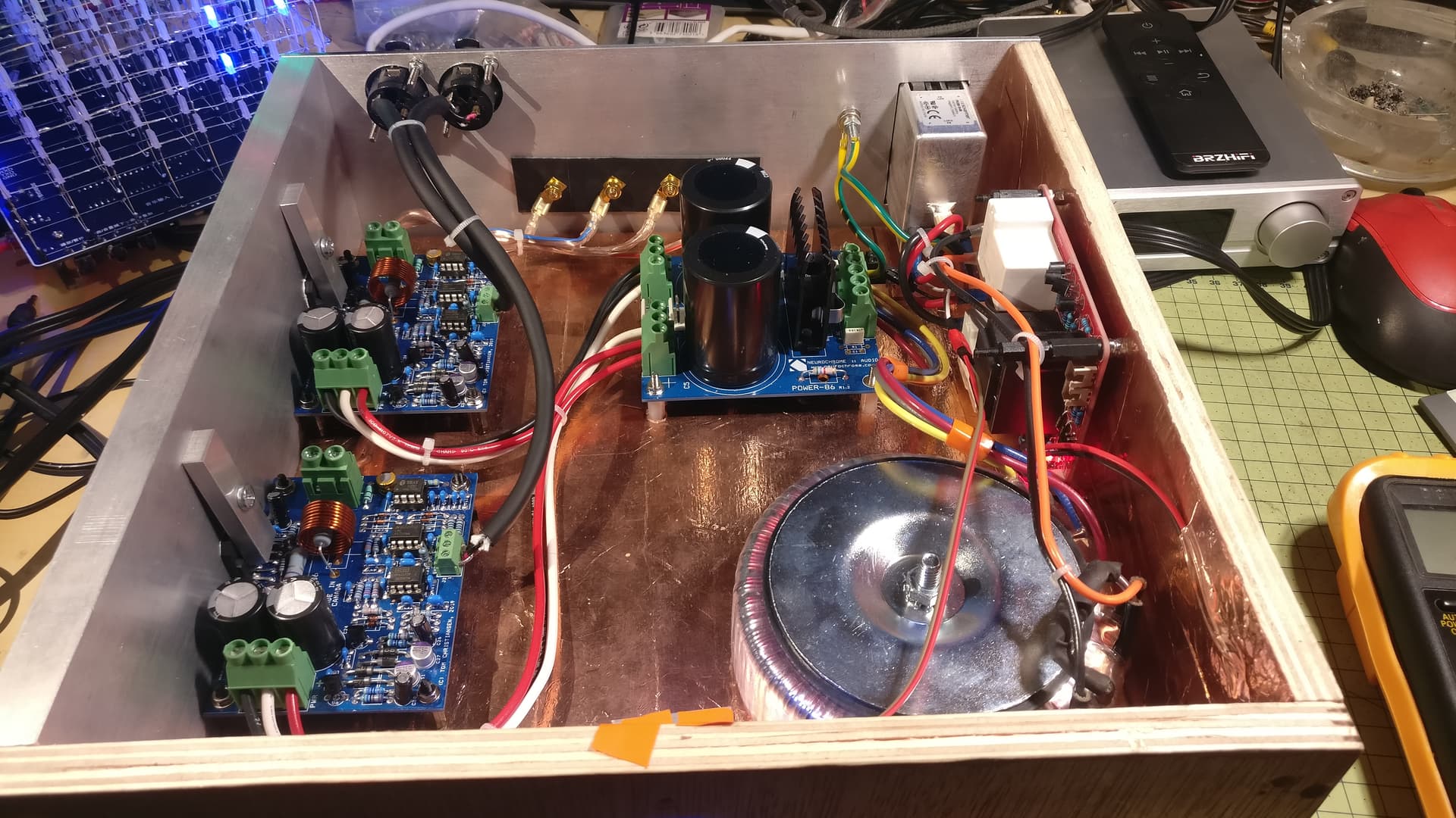
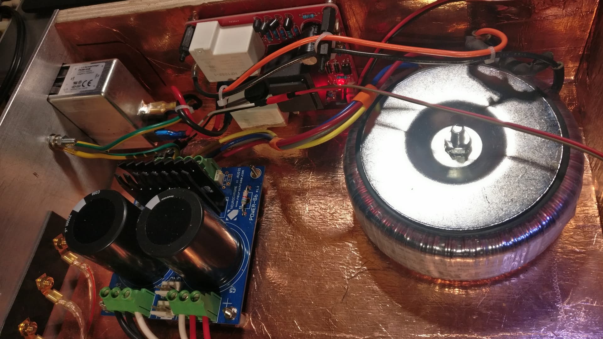
On the side with the transformer there is the mains input terminal. The red board with the white box on it is a soft start module whch slowly charges the caps before it opens the relais to limit the inrush current. That’s a but overkill because under 200VA transformers the current on startup is not so bad. But it should prolong the life.
From the red board it goes into the transformer and from there into the rectifier with the big caps.
On the left there are the 2 amplifier boards, one per channel. There is no real heatsink at the moment, there should be enough material for cooling since I don’t plan to run it on high levels for long times.
Input is balanced, output is 2x40W to 8Ohms or 2x75W to 4Ohms. Nothing spectacular, but probably enough for most living rooms.
Conductive glue copper foil to create a shield on the wooden parts and a switch from a mod to turn it on and off.
Mega +1.
No no Sir, WELL thought out. Overbuild For The Win.
Ahhhh, I see. Very nicely done Sir, VERY nicely done.
Nice.
Sweet. Almost doubling, I like it.
I’m assuming that is a class A/B ?
For the electric testing I had to make sure I have the correct voltages on the right pins, continuity tests to make sure there are no shorts and then a 100mV signal of 400Hz to measure the gain. The DC offset is near 0.000 because the boards use a DC servo circuit. This feature was one of the main reasons for me to choose this amp. Most diy projects require a manual adjustment of the bias which I was a bit afraid of. This is where soldering by numbers stops and you need some proper knowledge so I tried to avoid that.
OMG, you just reminded me (derail, … kinda).
In a previous vehicle build I did, I had a total of 2.5F of caps. (2) 1F for the sub amps, and (1) 0.5F for the front stage amps. 2.5F IS a rather large bomb, hehe.
I forgot to DISCHARGE them before I took the truck in for service, some random airbag recall or whatever, and FORGOT they would have to disconnect the batt terminals, per their spec. Well, hehe, they did, and apparently were completely UNREADY for the hehe INRUSH of 2.5F of caps when the cable touched ground. Hehe, OOOOPS.
Luckily the truck was super clean, and the dealer actually replaced the main positive cable and clamps, that had arc welded.
The CAPS did NOT detonate, did not split, bulge or in any way fail. They did what they do, and that was PUSH as hard as they could.
Excellent choices! Much better than recalibrating periodically as tolerances evolve. Remember when if you bought a Macintosh they would come out an calibrate it every year? Many, many moons ago.
Now, that’s amazing!
Yep, class A/B chip amp, using an LM3886 paired with an opamp for error correction. This is where the LM3886 suck a little apparently. But that’s just repeating what I read on the developer’s website and the manuals. No real idea what I’m talking about here.
Check out his website, neurochrome.com. I was just looking for a decent diy project but this guy has a really good reputation and his stuff is in a lot of custom amps for a lot of money.