Weird battery question

Note: 3.5 Volts is the battery voltage corresponding to (approximately) 1/2 of the full-charge level. Sobering.

.

Following up on information about the Molicel P26A (text below from one of The Mooch’s test reports):

if you run your cells down to 3.5V-3.6V (when put on the charger), and wanted a slightly more consistent vape that could run for longer, then the P26A is worth trying. … The datasheet lists the minimum capacity at 2500mAh and typical capacity at 2600mAh. The six P26A’s I tested delivered 2607-2641mAh at 520mA (0.2C) down to 2.5V. This is great consistency and they all easily met their minimum capacity rating. … I am rating this Molicel at 25A continuous with a temperature-limited rating of 35A as long as you stop before the cell reaches 60°C. …

… The P26A is my choice for best all-around 18650, for up to 25A or 75W per cell. The combination of its great performance along with its availability from authorized Molicel vendors makes it the best choice in my opinion for moderate to high power use in any device. We don’t have to worry about getting low grade, counterfeit, or old cells and Molicel is willing to sell to the vaping community. No other battery OEM is openly willing to do that.

Source: https://www.facebook.com/batterymooch/posts/bench-retest-results-molicel-p26a-2600mah-18650beats-vtc5a-best-all-around-18650/2332974400325466/

Have carefully eye-balled the battery Voltage discharge curves of the Molicel P26A as compared to the Samsung 30Q and 25R. At a (discharged-to) battery Voltage of 3.3 Volts, with a 5.0 Amperes continuous current discharge rate, the 30Q fares just a tad better than the 25R (mostly providing more capacity at battery voltages below 3.3 Volts, ranging down to generally in Mods not utilize-able 3.1-2.9 Volt levels).

Although the Molicel P26 has a high maximum continuous discharge current rating from testing, and may be a desirable item for users drawing a lot of battery current in high Wattage devices - the voltage discharge characteristic of the Molicel P26A at a 2.5 Ampere continuous discharge rate is almost identical to that of the Samsung 30Q at a 5.0 Ampere continuous discharge rate (in both cases, considering battery voltages of 3.3 Volts or higher). Thus, for typically lower Wattage usage applications, the Samsung 30Q (from the published specification data) appears to be notably better than the Molicel P26A. When considering usage below 3.3 Volts down to 3.1-2.9 Volts, both 30Q and 25R appear to be a notably better choices than P26A.

Note: It may be that the discharge data graphed and relied upon on the P26A data-sheet is the result of (actual) testing results - whereas Samsung’s 30Q and 25R data-sheets state that the discharge curves shown are (some kind of desired product performance) “target” - implying that Samsung’s produced battery units may perhaps be less “robust”. Such a situation (with perf. data held proprietary) would not surprise. :thinking:

If the (apparent, based upon possibly “squirrelly” Samsung data) differences between the 30Q/25R and the P26A (if/when these batteries are usable down to 3.3 Volts) is a real thing, then those characteristics might indicate a design trade-off, where higher continuous Current capability exacts something of a price where it comes to discharge Voltage over time characteristics, and - since some Mods appear to have low-battery voltage cut-offs of ~3.5 Volts or so - that (in practical effect) limits by lowering (effective) battery capacity.
6 Likes

Not sure if you covered this or not. I apologize but I’m a tad ADD tonight can’t wade through your entire post. Did you cover the point that many mods use a “dynamic” cut off point? Batteries will tend to show full or nearly full voltage under no load. Under load they very well may drop well into cut-off regions of voltage e.g. ~2.5V. YiHi mods actually show this as their battery bars are dynamic and monitor battery voltages during vape as well as between vapes.

6 Likes

Ogre, I’m not sure if I understand quite what kind of behavioir you are describing.

Not sure if the following (from the POS Pico 25 User Manual) may possibly relate at all (?):

Weak Battery Alert: in all vaping modes, when the device is working with an atomizer
and the voltage of the battery drops below 2.9V, the screen will display “Weak Battery”.
Meanwhile, the output power will be reduced accordingly.

Perhaps they just mean that when the battery voltage dips to 2.9 V (at all, ever), don’t expect very much.

Low-voltage Protection: when the voltage of the battery is below 3.3V, the screen will first display “Battery Low” and then “Lock”. Charge the battery to unlock the device.

… and (thanks to POS documentation) it’s not clear whether eLeaf’s info above makes coherent sense. According to the latter statement, the system would shut-down at the higher 3.3 Volts (perhaps when battery voltage after cessation of load does recover to a voltage higher than 3.3 Volts). That criteria might make (independent) sense - a “Weak Battery” annunciator when (instantaneous) battery voltage crosses 2.9 V.

2 Likes

More confusion piled on, lol via user manual. Forty pages of more mud inside! Simply from watching my pico’s (none of which are the 25 of course) “weak battery” appears to be invoked if the voltage reaches a low threshold any time during a vape. It seems to indicate that there is not enough voltage at the battery for the regulator to achieve the desired power. I have no idea what the 3.3V reference might indicate. I’d need engineering design documentation to decipher that.

3 Likes

My Sigelei 30W Minis as well as the Pico 25 both seem to refuse to operate when the battery (then pulled from the units, and quickly measured for Voltage) is approximately 3.3 Volts. (I guess) that the Pico 25 (also) generates a “Weak Battery” alert for any (even brief) excursion of battery voltage below 2.9 Volts. “The Mooch” reccomends not using below 2.9 Volts (with 2.5 Volts considered "rock bottom, and where re-charging could possibly become dangerous).

The voltage-drop across a (bipolar) semiconductor junction could approach ~1 Volt - but they much more likely use the somewhat lower voltage-drop of a MOSFET junction. (In a straightforward true hardware "Bypass Mode"anyway), that voltage-drop (across the switching channel) would directly subtract from the battery power-supply voltage - limiting the voltage that can be developed across the composite coil-load. When my Sigelei 30W Minis get to that situation, they will (seemingly kind of randomly, actually) flip into the (not true) “Bypass Mode”. Sudden occasional unexpected bursts of vapor as the PWM falters.

2 Likes

Recharging become dangerous or simply not happen as the battery has been discharged beyond recovery. The 3.3V threshold means nothing to me. Could be some design parameter for some chipsets, don’t know. Not sure either regarding junction drops. In the day we all figured .7V silicone PN and .3V germanium PN. Haven’t kept up with PN doping since then so I can’t really comment.

3 Likes

Remember that ~0.7 Volts is at a few milliAmps current (let’s call it 10 mA), increasing at ~60 mV per decade (of geometric growth). At 10 Amperes current, one needs to add ~0.18 Volts (to make ~0.88 Volts). Also, voltage-drop developed across the internal series Resistance increases the composite voltage-drop.

MOSFET voltage drops (almost certainly being widely used in the widgets) are somewhat lower valued (due to lower channel resistances achievable using FETs). I’ll look into what kind of voltage-drops we can expect.

2 Likes

Ya, sorry, too many assumptions here. Without the engineering prints I can’t guess at this.

4 Likes

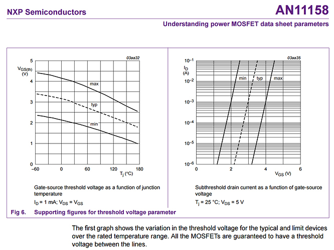
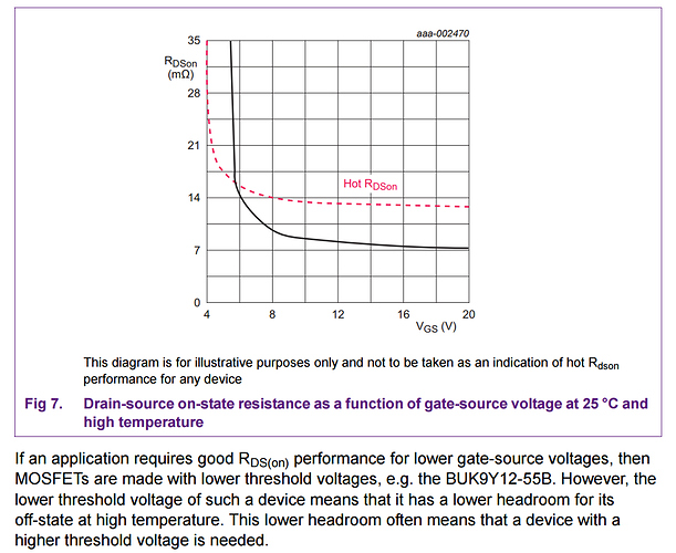
Here is a pretty good (and an also relatively current, 2017) information source. See Section 2.6 (Electrical Characteristics) on (main document) Page 12 of this Nexperia MOSFET Application Note. See “R(ds) ON”.

1 Like

Agreed, without a doubt.

/generally speaking

What little I can say is that, given what I’ve seen, the selected “safe cutoff” appears to not only vary highly, but is randomly, and seemingly arbitrarily chosen, depending on the manufacturer.

Over the last few years, I’ve seen from 3.4v, down to 2.9v, and “unique variances” in between.

An example of the latter would be what’s exhibited by the Smoant Cylon’s output ramping.
When the battery meters get to about two bars (basically the 40% marker, since there are 5 bars), you notice a slight drop in power (output).
This happens once more when you get to the 20% marker (a single bar). *Note: I’m pretty sure I included battery voltages in my review way back when… But nonetheless, it’s an example of a unique implementation of the way they sometimes manipulate the PSU section.

I think the key for the average user is, just make sure to verify the operation of a newly acquired mod, by taking a reading of batteries that are freshly pulled from it after getting a low battery message (either with your charger, if it has the ability, or even with a cheap voltage meter from your local hardware store). At least you’ll have some idea of how the mod alerts, at roughly what voltage point it considers low. And whether or not it’s something you need to be aware of (very rare in relation to recent* regulated mods).

*it might be a relevant concern with mods from 2015 and before though. But I would be surprised by most anything recent.

4 Likes

More generally (without specifics as to particular numerical values):
Metal Oxide Field Effect Transistor: What is RDS(on)?

2 Likes

You get a sense of “discrete” shifts to lower powers (in some mode where power is specified) ? If it was “continuous”, it (might) seem hard to determine which of the two (the display meter value, or the sense of available power) “causes”, or perhaps merely represents, the “operational state” of the other ?

PSU is initialization for … ?

2 Likes

I’ve given thought to putting the second channel of the scope across the output of the batteries to watch the correlation between battery and load but then dismissed the idea per the hassle involved. Like you’ve observed every mod is different. I’ve got a old Wraith squonker that I’ve pretty much relegated to the shelf for a long time as I could only get about 50% battery life out of it. Recently, I put a more efficient recurve on it with a build just over .5Ω and used it at 35 watts where it happily used the battery down to about 20% per meter. The DNA 75C Therion is much the same in replay mode. Save a hit with a nice warm atty and then later trigger the unit cold and it’s common to get low battery at 50% charge. Drop out of replay where the unit isn’t boosting to compensate for the loss of resistance and vape on down to 30% easily.

3 Likes

From the above-linked Nexperia MOSFET Application Note:

.

V (Gate to Source) Threshold - [ V(gs) TH ]: Something in the range of ~ 3 Volts to “turn on”:

.

Resistance (Drain to Source) On - [ R9ds) ON ]: Looks like something in the range of 30 milli-Ohm:

.

So (as a rough guess indeed), minimum battery voltage of ~3.0 V + ( 3x10^(-3) ) x Current [Amps].

For 10 Ampere current draws, the sum of the two voltages equals ~3.3 Volts ! … :nerd_face:

2 Likes

Sorry!
Power supply unit (or section, in this case).

I do. But it’s not during a puff. It’s a shift between puffs. (I first noticed it “thanks” to chain vaping…)

That’s what led me to believe that it was some predetermined voltage reading, rather than current based. And honestly, I would do it the other way (if I had a say), as I believe the drain would be reflected faster in current monitoring.
Like yourself, hard to say anything with certainty.

I think it was probably cheaper to do it this way. But yes, in either case, I would agree that it’s merely a representation.

I really wish the 75c (in a 21700 format) would have gotten better traction. Not only because I really REALLY respect and trust Evolv, but because at least then, we could go to them and get accurate and informative answers (in cases such as these). Getting answers from China on this type of subject matter?? Ha! Yeah right.

2 Likes

That would seem to imply to me that they’re actively monitoring the available current in a boost type circuit. :thumbsup:

:thinking: Though the latter (30% comment) seems to imply they’re changing to a voltage monitoring system non Replay mode. Odd.
I’d be interested to see what you find if you pursue this further.

3 Likes

Absolutely. Indirectly of course, via voltage and resistance correlation. In replay mode the DNA will boost like hell to attempt to achieve the initial hit of the warm saved curve. You can see this easily by looking at puff data.

3 Likes

Once you drop out of replay mode the mod will act like a simple vw mod and provide a standard ramp time to voltage necessary to deliver set wattage to existing resistance. I replay mode the dna will smack the coil with a boosted voltage to drive the resistance up to the starting resistance of the saved warm puf trying to recreate the original resistance curve.

4 Likes

Synchronicity struck me late in the night watching the tech talk roll on by, and I imagined adapting the (great) “Polk Salad Annie” by Tony Joe White to “Puff Data Daddy”. Dig it now ! … :clown_face:

Here he is performing it live some 12+ years later. It’s got a great infectious kinda cajun groove.

3 Likes

Holy geez.

3 Likes