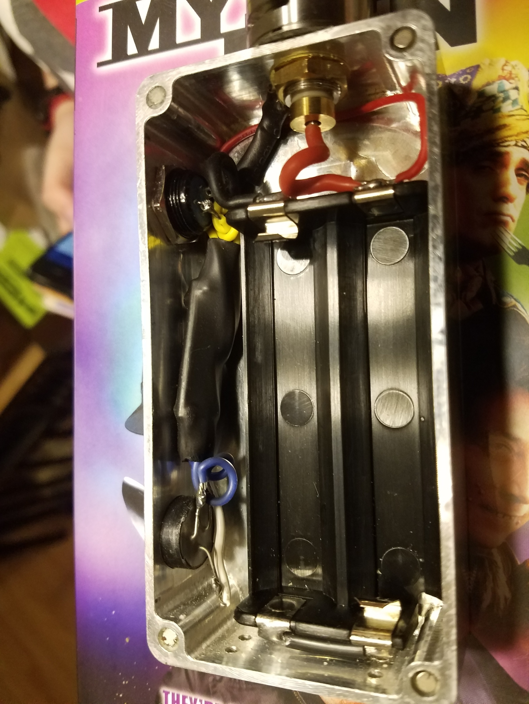
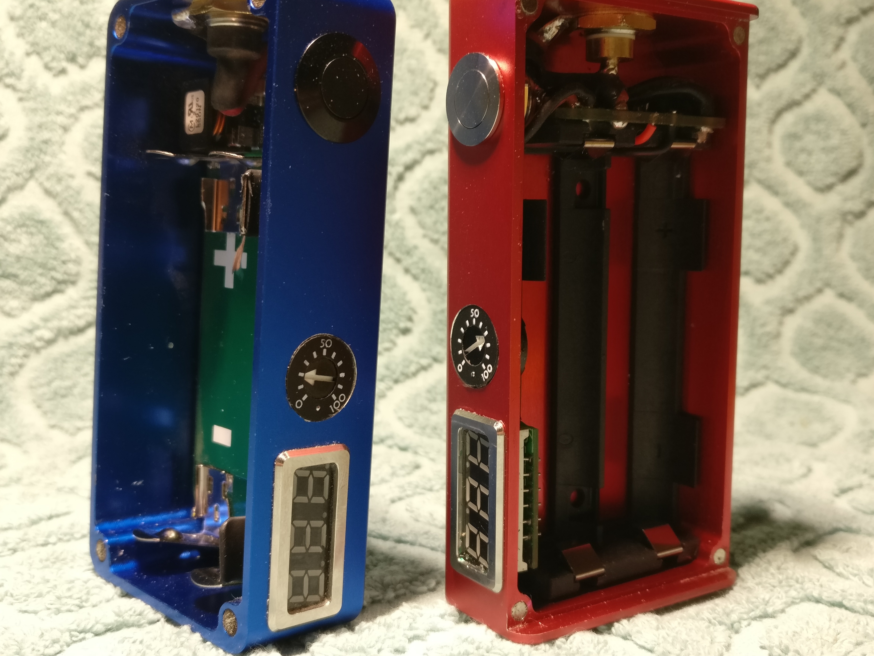
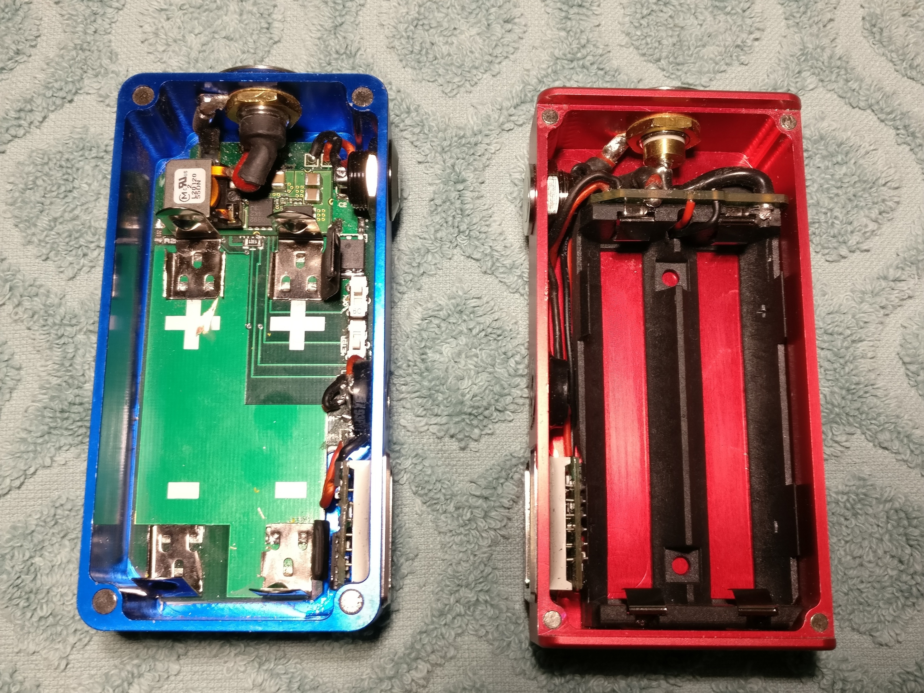
Sorry it took so long…hands are full, but here is two pix. Board on left, shrink wrapped.
1 Like
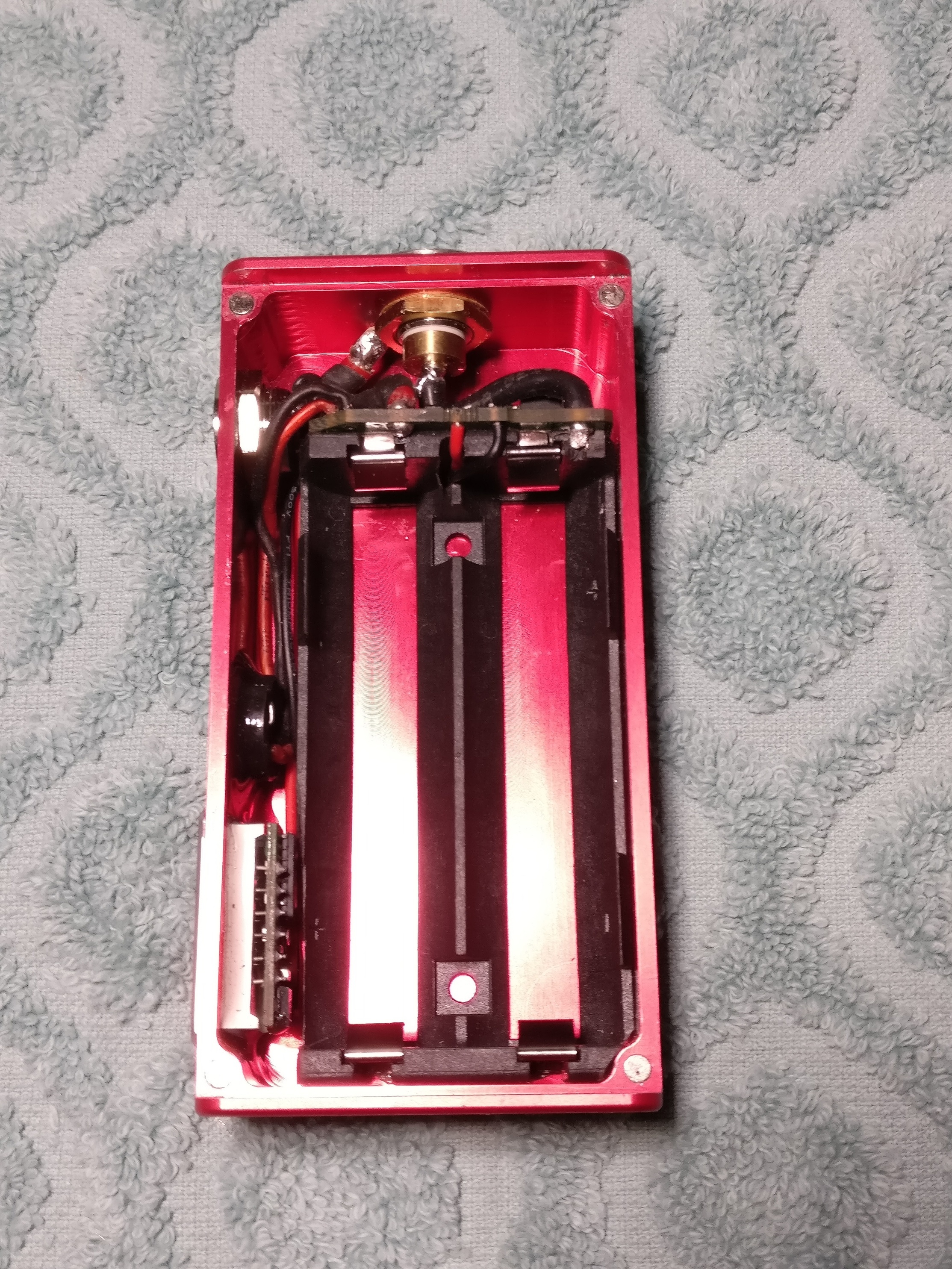
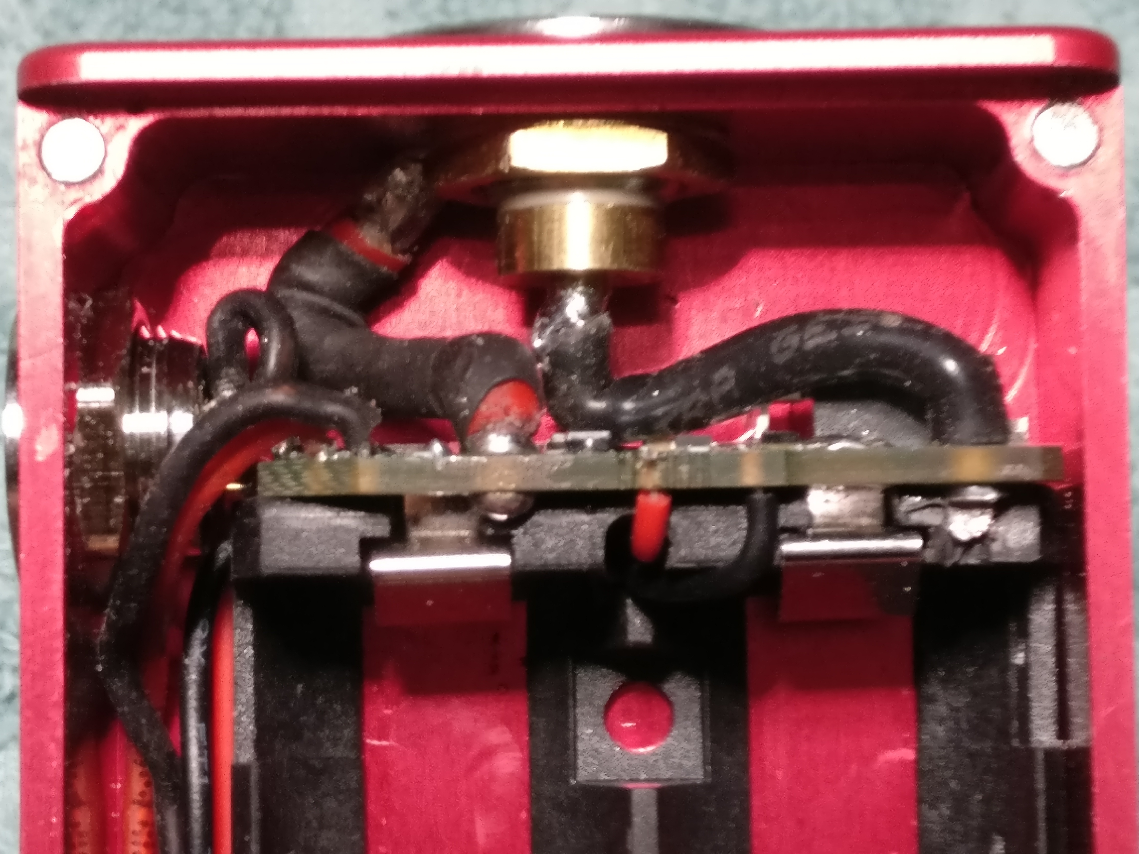
I haven’t, I think they are perfect on top of the sled…wanna see pix?
Yes, please!
This was my first sled board done, so not as pretty:
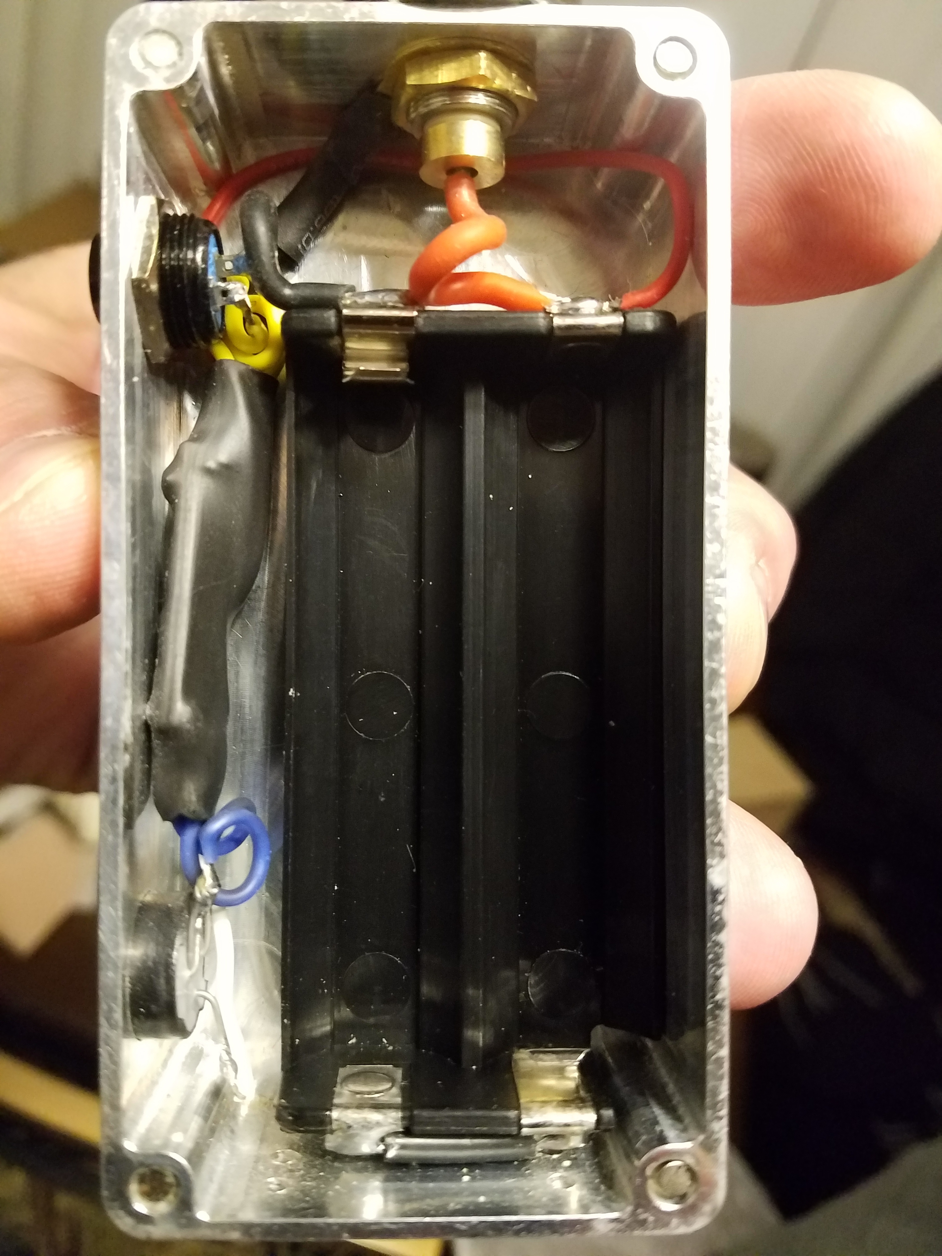
After I knew what I was doing:
Headed to work…hit me if ya need me!
2 Likes
Very nice!
Can’t stay…headed out, but had to say VERY NICE!
How does it hit?
2 Likes
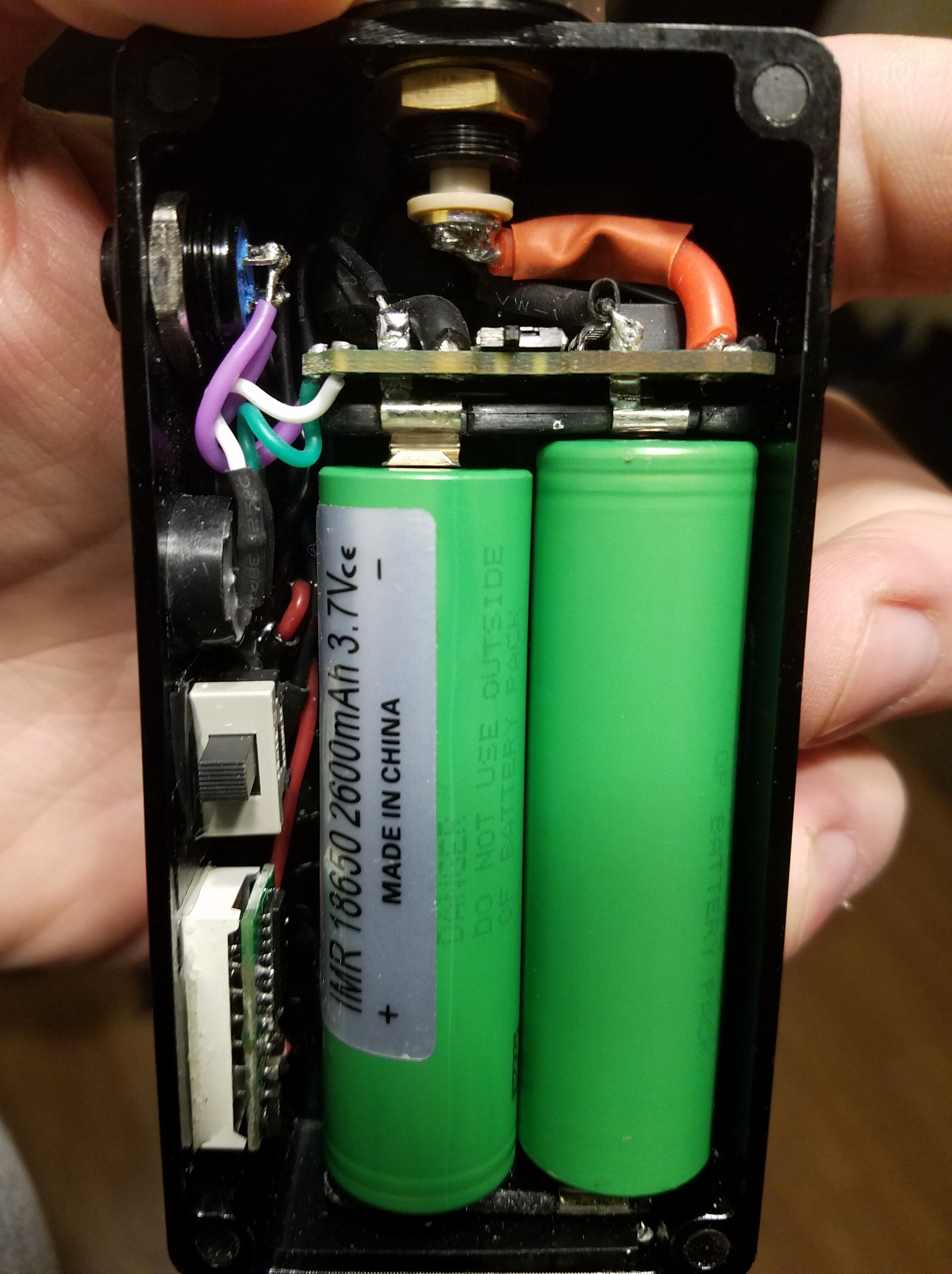
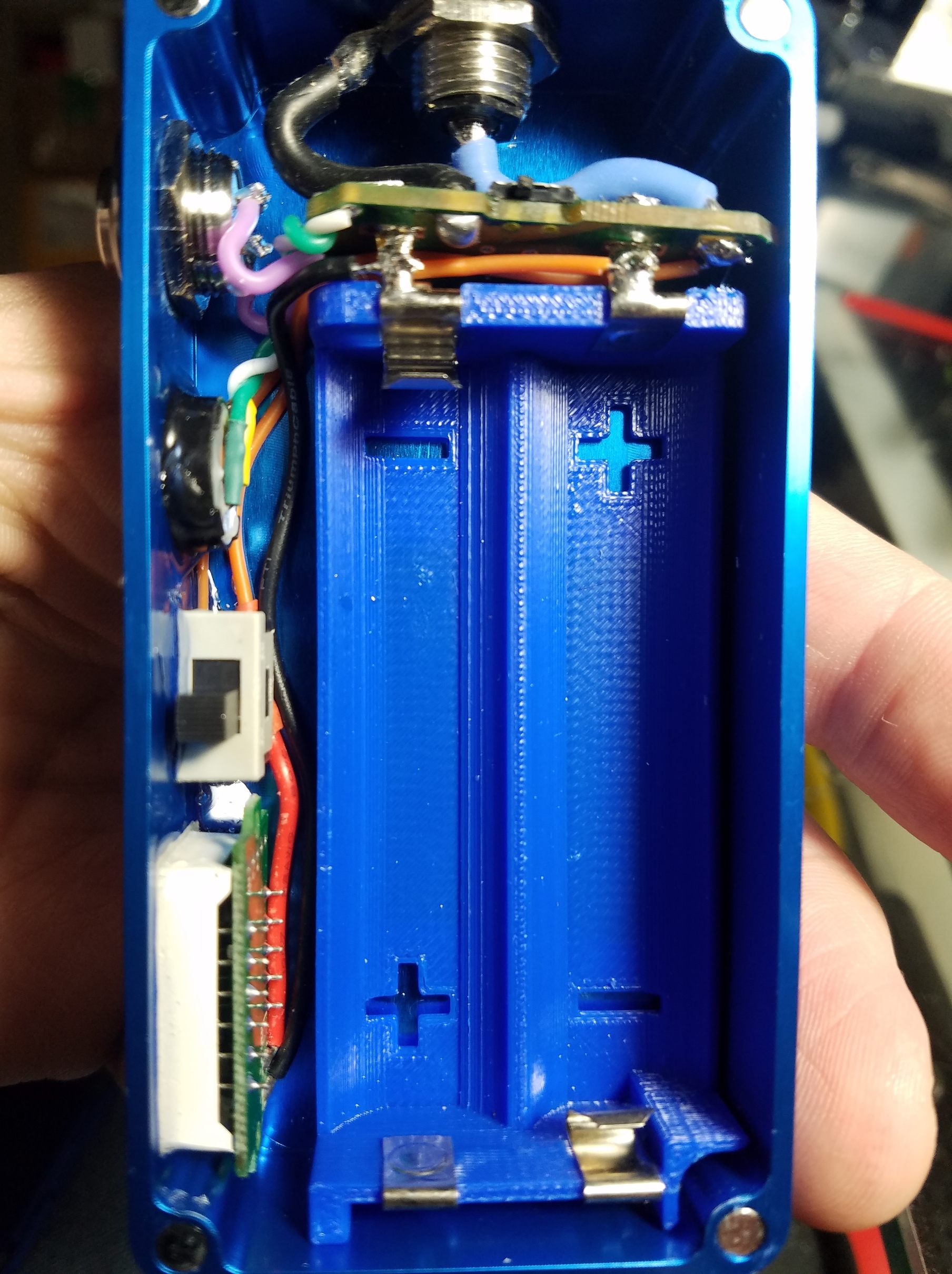
Working very well. This is the new IPWM board from Big Al. The blue one with the Murata chip works well, too but it doesn’t cut off when the batteries are going flat. Not sure if that is a problem but it could discharge the batteries too low.
Ok @Whiterose0818, I know you’ve told me before but I forgot, on a potentiometer is the pin on 0% side negative and 100% side positive or do I have this backwards. It’s the only thing about this build that’s hanging me up and I can’t find any info on this. I looked over several places and can’t seem to find the answer but then I thought “I know who does.”
I’ve not seen it referred to as polarity…can you show me the diagram you are referring to?
1 Like
Not looking at a diagram, I thought the way you said to tell which pin is negative is to look at the potentiometer from the back with the pins being looked at top side like this,
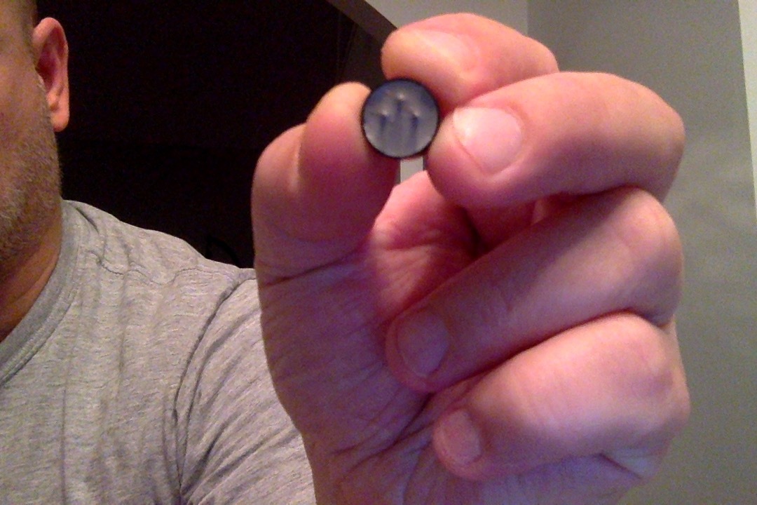
the one on the right is negative ?, left is positive? and the right side is same side as 100% and the left side is same side as 0% and that’s what I’m saying but I’m still not sure which ones are negative or positive.
No…quit that. There is only negative when you look at a Smart PWM build.
If you look at it the way you have it (I usually do the other way around, but the top, single pin is the wiper. Left is 0% and right is 100%.
Look at one of the left or right pins…then slowly turn to see whare it’s at…it’ll be the corresponding variable on the other side. The middle pin, whether it is top or bottom in the configuration, is always the wiper.
1 Like
@Beaufort_Batches
I redid the wiring diagram for the Smart PWM v2.2, have a look:
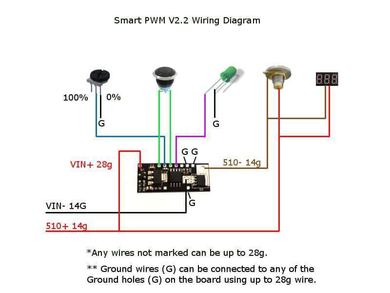
Is that better?
Also, I haven’t heard from you…how’s the build going?
1 Like
I’ve been so busy with business and family. So far, I only have the positive and negative wires soldered to the chip. Looks good too, I let a bit extra through and cut it off neatly after solder cooled. I am hoping to dig into it more tomorrow. Thanks for the diagram…BB…
May i just throw a random general question in:
In the manuals of many boards they mention that there is no over current protection on the board and that it should be added for safety reasons. Is it correct that over current protection is only necessary if the coil is under… let’s say 0.1Ohms? In other words, I can avoid dangerous currents by just keeping the current below whatever is considered dangerous? (60A for most boards or whatever the current limit of your batteries is).
So with a 0.1Ohm build i would reach this limit @ 6 volts? (6V/0.1Ohm=60A)
So you would rather limit the minimum resistance to let’s say 0.15 or 0.2Ohm? Are you using any physical over current protection or are you telling your customers they can’t use builds below x Ohms?
1 Like
Since I was using a lot of electronic mods where you get all the data on the screen and I mostly used Power mode I could’t really cope with the voltage settings on a PWM mod. I need to know how much power in Watts are actually used and also I wanted to know how many Amps are withdrawn from the batteries to avoid problematic/dangerous values.
So i fiddled a little spread sheet together with 2 different formulas.
The first one gives you the current in amps and the power in Watts after entering Voltage and resistance of the coil. This is just an info thing if you a curios how many watts the mod is actually using.
The 2nd one is to get an idea of which voltage to set on the PWM device. Enter the desired Watts and the resistance of the coil and it gives you the Voltage you have to set to get the Watts you want. Additional info is the current to see if it goes towards the 60Amps which are the limit for many 2x18650 mods.
1 Like
Good work. There should be no excuse for people not knowing how much current they are drawing, with their builds.
You just made it easier for them to know. This should be stapled to the beginner threads.
Not trying to dismiss your efforts by any means…but here is the website I use to calculate those variables:
http://rapidtables.com/calc/electric/watt-volt-amp-calculator.htm
2 Likes
Website shmebsite 
I wanted something offline because i want to be independent from the internet. I may not have the internet when i need the calculator.
1 Like
@Whiterose0818, can you justify why this Potentiometer is worth over 22 bucks not counting shipping? I see some people have started using this and am wondering if it’s overkill for what we are using them for?
ive seen a few of these in use…i guess people like the big knob.
1 Like